Creative Nomad Jukebox Zen
Earphone Socket repair
Karen has a bit of a "thing" about these players and has several, one in the hifi cabinet, one in the car, one in the handbag...
This one has seen better days, screen is damaged but still readable. More of a concern was the earphone jack which was dead in one channel and intermittent in the right.
Thanks to The Bishop for his guide which was a big help. However Karen's player had a slightly different problem with the jack... So I hope this guide will help if you have the same problem.
|
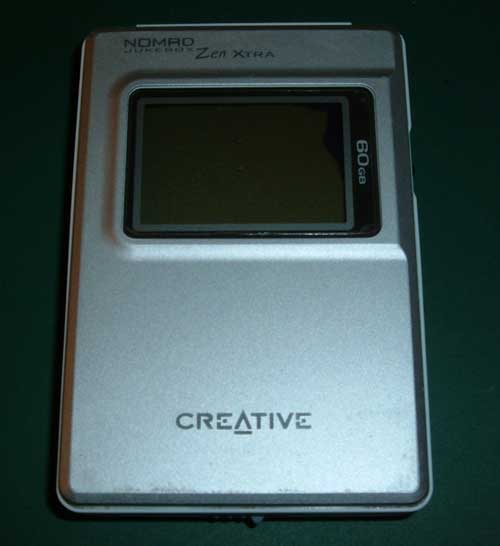
| Karen's Nomad with an intermittent earphone jack... From here on known as the offending beast... that's the Nomad not Karen. I think the player had taken quite a thump at some point, the screen has lost the back light and the LCD is damaged too. Not much can be done about the screen apart from replacing the whole logic board but that's going to cost as much as a second hand player. If you want to go down that road they are available here. |
 |
| The strip down starts. Battery out. |
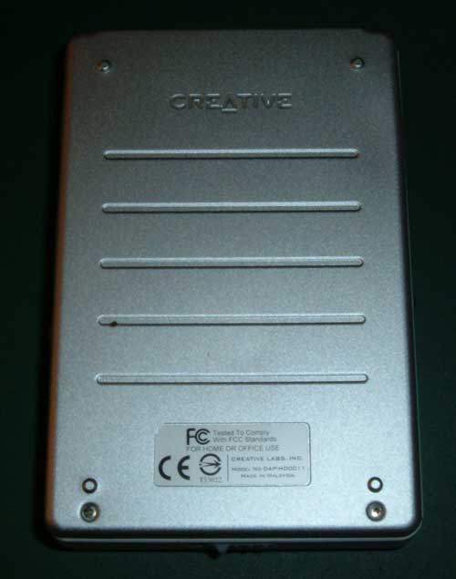 |
| Flip it over... |
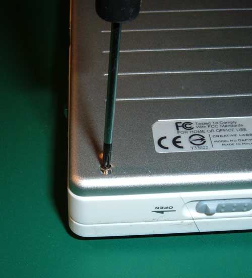 |
| ...and unscrew four screws with a PH 000 screwdriver. |
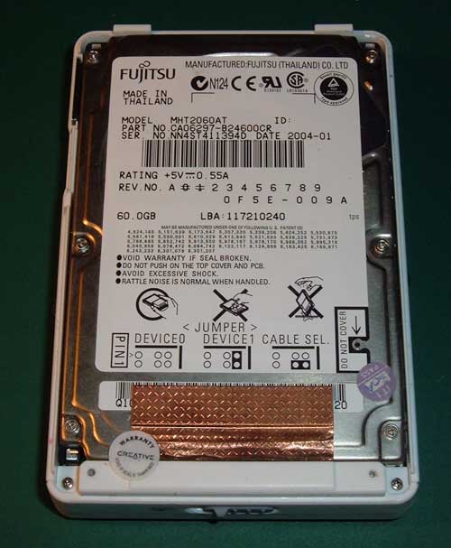 |
| Here's the HDD and two more PH 000 screws at the bottom that need to be unscrewed. |
 |
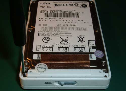
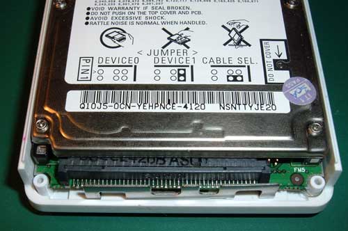
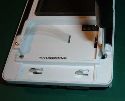
| These stickers mean nothing to me. |
 |
| So unscrew left and right screws... |
 |
| ...and remove the latch mechanism. |
 |
| Flip the unit over... |
 |
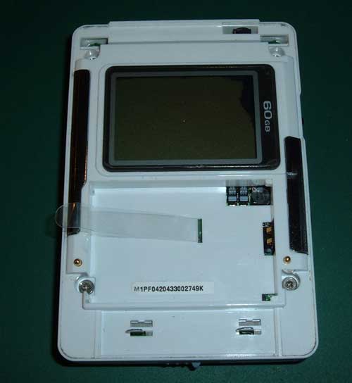
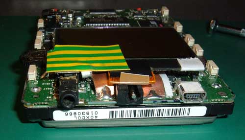
| and unscrew the four PH 00 screws. |
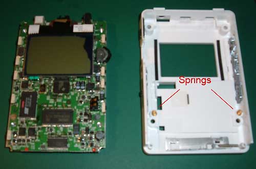 |
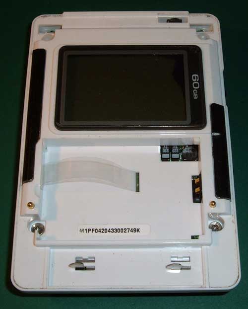
| On the left you can clearly see the screen is damaged in the top right. The springs on the inside of the case have a tendency to fall out, and roll away. |
 |
| At this point I realise that starting this project while I am waiting for my new glasses may not be the best plan. |
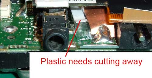 |
| There is a paper and plastic insulation strip right where I need to get to... |
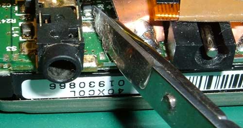 |
| ...snip! |
 |
| ....fold it back and tape it out of the way. I knew that earth tape would come in handy one day. |
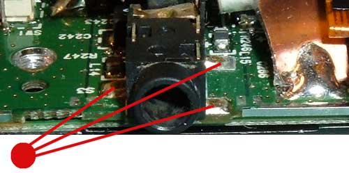 |
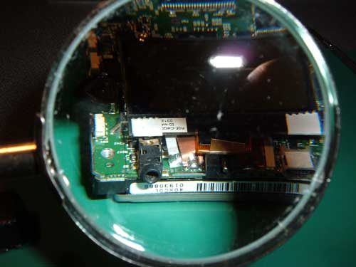
| These three tabs are the problem you can move the socket and see them lift away from the PCB... |
 |
| ...well you can see them lift away if you look really close. I tried re soldering the tabs but it soon became clear that I was soldering to copper that was free of the PCB. There was a good deal of swearing at this point. |
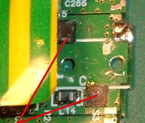 |
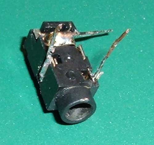
| So I removed the socket to see what was going on. The two brown squares marked here are where there should be two copper squares. They came away easy as anything the socket was only connected by one tab. |
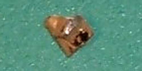 |
| One of the offending copper squares. Seeing the amount of strain you can get on these sockets I really wonder why designers keep insisting on mounting them to PCB and not bolt them to the case. |
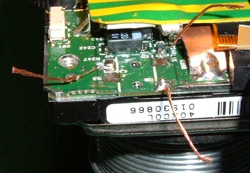 |
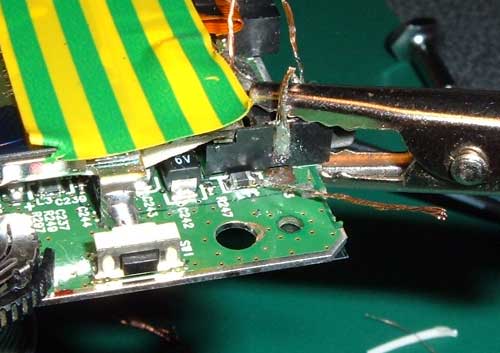
| So I soldered three wires to the PCB on on the good tab and one each to the output of L14 and L15. |
 |
| Soldered three wires to the socket. |
 |
| Trimmed the wires and tinned them. |
 |
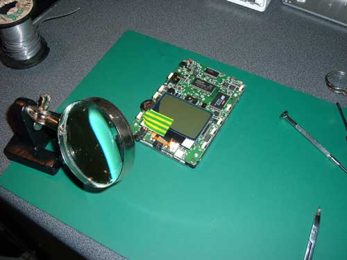
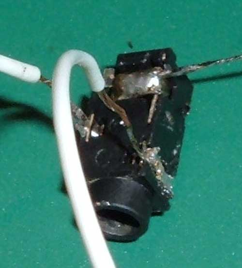
I decided to glue the socket in place and here it is clamped while the glue sets. |
| Once the glue is set it should be an easy job to solder each of the 3 pairs of wires together, rather than try and solder 6 joints with the socket in place. |
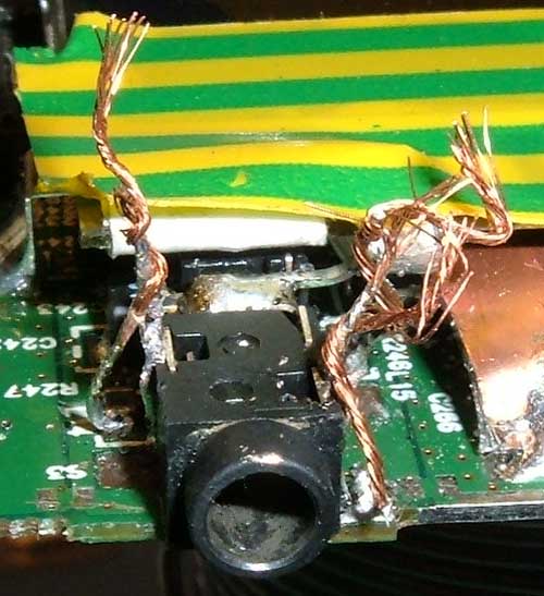 |
| Looks a bit of a mess but remember that socket is only 3.5mm in diameter so the wire is less than 1mm. |
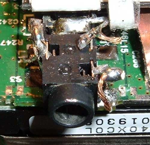 |
| After soldering, trimming and folding over. |